- 您现在的位置:买卖IC网 > Sheet目录1222 > ISL1208EVAL (Intersil)EVALUATION BOARD FOR ISL1208
�� �
�
�?�
�Real� Time� Clock� USB� Evaluation� Board�
�Application� Note�
�June� 20,� 2005�
�AN1176.0�
�Introduction�
�This� evaluation� board� provides� a� platform� for� testing� the�
�ISL1208� and� ISL1209� Real� Time� Clock� (RTC)� devices.�
�Device� features� include� a� crystal� oscillator,� clock� and� date�
�counters,� and� an� alarm.� The� ISL1209� device� includes� an�
�event-detection� feature� for� recording� the� time� of� an� event.�
�The� evaluation� board� provides� a� platform� to� test� all� of� these�
�functions,� as� well� as� evaluate� device� performance� criteria,�
�such� as� long-term� clock� accuracy.� Hardware� options� such� as�
�battery� and� crystal� types� can� also� be� tested.� The� software� is�
�designed� to� allow� easy� setup� and� monitoring� of� all� major�
�device� functions.� The� two-piece� construction� utilizing� a�
�motherboard� and� a� daughtercard� enables� the� board� and�
�software� to� operate� the� RTC� device� residing� on� a� remote�
�board.�
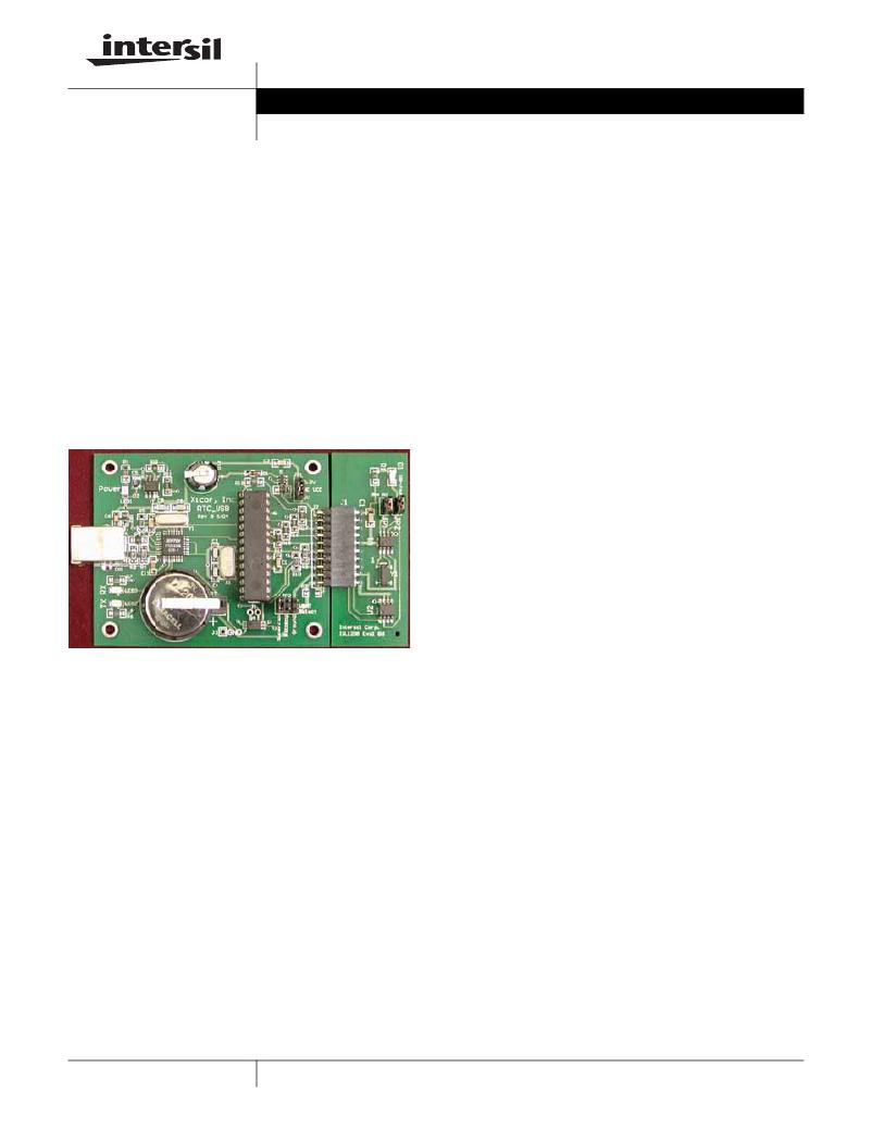
�FIGURE� 1.�
�Operation� of� the� RTC� Evaluation� Board�
�Hookup� and� Power�
�CONNECTIONS�
�The� eval� board� consists� of� a� motherboard� and� daughtercard�
�and� these� need� to� be� connected� together.� The� evaluation�
�board� uses� hardware� and� software� from� FTDI� for� USB�
�communications� and� these� drivers� must� be� installed� on� each�
�PC� that� talks� to� the� RTC� eval� board.� A� USB� cable,� with� type�
�A� and� B� connectors� on� the� ends,� is� required� to� hook� up� the�
�board� to� a� PC.� The� cable� should� be� connected� to� the� PC� first�
�and� then� to� the� eval� board.� Once� connected,� LED1� will�
�illuminate� indicating� +5V� power� is� available� from� the� USB�
�cable.�
�POWERING� DOWN�
�The� daughter� card� contains� backup� power,� consisting� of� a�
�battery� or� supercap.� When� powering� down,� the�
�daughtercard� will� operate� off� the� backup� source� determined�
�by� JP2� (after� the� V� CC� voltage� discharges� from� the� V� CC�
�supply� capacitors).� If� the� user� wishes� to� totally� power� down�
�the� RTC� device� once� V� CC� is� removed,� then� either� remove�
�the� daughtercard� from� the� motherboard� or� set� JP2� to� GND.�
�Keep� in� mind� there� is� a� decoupling� capacitor� on� the�
�daughtercard� (0.1μF)� which� must� discharge� fully� before� the�
�RTC� device� stops� operating.� This� discharge� time� can� be� up�
�to� one� second� when� using� a� V� CC� of� 5V.� Note� that� when�
�powered� down,� the� RTC� board� cannot� be� monitored� by� the�
�RTC� software.�
�Installing� the� RTC� Software� and� USB� Drivers�
�USB� DRIVERS� AND� COM� PORT� SETUP�
�Insert� the� Intersil� RTC_USB� CDROM� in� the� PC� to� be� used.�
�Open� the� folder� “Install� USB”.� Then� open� the� ZIP� file�
�“FTDI.zip”.� Extract� this� set� of� files� to� a� separate� folder� on�
�your� main� hard� drive.� For� example,� create� a� folder� titled�
�“FTDI”� on� your� C:� drive,� then� extract� the� contents� of� the� ZIP�
�file� to� that� folder.� In� the� “Install� USB”� folder,� there� is� a� pdf� file�
�titled� “Windows� Drivers� Installation� Guide”.� Open� that� file�
�and� follow� the� instructions� for� the� FTDI� 232� device� (you� will�
�need� to� connect� the� RTC_USB� Eval� Board� to� your� PC’s� USB�
�port,� this� will� bring� up� a� prompt� to� install� the� USB� hardware�
�and� software� drivers).�
�Note� that� both� a� hardware� AND� a� software� driver� need� to� be�
�installed� for� correct� USB� operation.� These� are� two�
�procedures� that� are� best� done� sequentially� per� the� FTDI�
�Installation� Guide.�
�Once� the� USB� drivers� are� loaded,� locate� the� RTC� program,�
�titled� “Intersil� 12xx_2.exe”� on� the� CD.� This� program� can� be�
�placed� anywhere� on� the� PC,� or� may� be� run� from� the� CD.�
�Double-click� to� execute� the� program� (note� that� the� “.._2”�
�may� be� changed� as� the� program� is� updated� and� the� revision�
�changes).�
�After� starting� the� program,� an� error� window� may� appear�
�indicating� that� a� certain� COM� port� is� not� available.� Dismiss�
�this� window� by� clicking� “OK”.� A� timeout� error� may� follow� and�
�this� should� be� dismissed� as� well.�
�On� the� Intersil� RTC� Data� Analyzer� main� window,� click� on� the�
�“Setup”� pulldown� menu.� Click� on� “Autodetect”� and� the�
�program� will� search� each� COM� port� to� find� which� is�
�connected� to� the� USB� device� on� the� eval� board.� A� small�
�“COM� Auto� Detect”� window� will� appear� and� monitor� the�
�polling� process.� Once� the� correct� COM� port� is� detected,� it� is�
�noted� in� the� “COM� Auto� Detect”� window� and� that� window� will�
�close.� If� you� wish� to� review� which� COM� port� is� being� used,�
�just� click� again� on� the� “Setup”� pulldown� menu.�
�If� no� COM� port� is� detected,� make� sure� the� board� is�
�connected� to� the� PC� with� a� USB� cable� and� that� the� board�
�jumpers� are� in� the� appropriate� places� (see� hardware�
�section).� If� there� is� still� no� COM� port� detected� after� any�
�1�
�CAUTION:� These� devices� are� sensitive� to� electrostatic� discharge;� follow� proper� IC� Handling� Procedures.�
�1-888-INTERSIL� or� 321-724-7143� |� Intersil� (and� design)� is� a� registered� trademark� of� Intersil� Americas� Inc.�
�Copyright� ?� Intersil� Americas� Inc.� 2005.� All� Rights� Reserved.�
�All� other� trademarks� mentioned� are� the� property� of� their� respective� owners.�
�发布紧急采购,3分钟左右您将得到回复。
相关PDF资料
ISL21007-EVALZ
EVAL BOARD FOR ISL21007
ISL21032-EVALZ
EVAL BOARD FOR ISL21032
ISL21060-EVALZ
EVAL BOARD FOR ISL21060
ISL21080-EVALZ
EVAL BOARD FOR ISL21080
ISL2109012EV1Z
BOARD EVAL 1.25V VREF ISL21090
ISL21400USB-EVALZ
EVAL BOARD FOR ISL21400
ISL28210SOICEVAL1Z
EVAL BOARD FOR ISL28210 8SOIC
ISL28217SOICEVAL2Z
EVAL BAORD FOR ISL28217 8SOIC
相关代理商/技术参数
ISL1208IB8
功能描述:IC RTC/CALENDAR I2C 8-SOIC RoHS:否 类别:集成电路 (IC) >> 时钟/计时 - 实时时钟 系列:- 产品培训模块:Obsolescence Mitigation Program 标准包装:1 系列:- 类型:时钟/日历 特点:警报器,闰年,SRAM 存储容量:- 时间格式:HH:MM:SS(12/24 小时) 数据格式:YY-MM-DD-dd 接口:SPI 电源电压:2 V ~ 5.5 V 电压 - 电源,电池:- 工作温度:-40°C ~ 85°C 安装类型:表面贴装 封装/外壳:8-WDFN 裸露焊盘 供应商设备封装:8-TDFN EP 包装:管件
ISL1208IB8-TK
功能描述:IC RTC/CALENDAR I2C 8-SOIC RoHS:否 类别:集成电路 (IC) >> 时钟/计时 - 实时时钟 系列:- 产品培训模块:Obsolescence Mitigation Program 标准包装:1 系列:- 类型:时钟/日历 特点:警报器,闰年,SRAM 存储容量:- 时间格式:HH:MM:SS(12/24 小时) 数据格式:YY-MM-DD-dd 接口:SPI 电源电压:2 V ~ 5.5 V 电压 - 电源,电池:- 工作温度:-40°C ~ 85°C 安装类型:表面贴装 封装/外壳:8-WDFN 裸露焊盘 供应商设备封装:8-TDFN EP 包装:管件
ISL1208IB8Z
功能描述:实时时钟 I2C REAL TIME CLOCK/ CALENDAR 8LD RoHS:否 制造商:Microchip Technology 功能:Clock, Calendar. Alarm RTC 总线接口:I2C 日期格式:DW:DM:M:Y 时间格式:HH:MM:SS RTC 存储容量:64 B 电源电压-最大:5.5 V 电源电压-最小:1.8 V 最大工作温度:+ 85 C 最小工作温度: 安装风格:Through Hole 封装 / 箱体:PDIP-8 封装:Tube
ISL1208IB8ZR5291
功能描述:实时时钟 I2CAL TIME CLK/CLNDR ALL BATRY MODE TESTS RoHS:否 制造商:Microchip Technology 功能:Clock, Calendar. Alarm RTC 总线接口:I2C 日期格式:DW:DM:M:Y 时间格式:HH:MM:SS RTC 存储容量:64 B 电源电压-最大:5.5 V 电源电压-最小:1.8 V 最大工作温度:+ 85 C 最小工作温度: 安装风格:Through Hole 封装 / 箱体:PDIP-8 封装:Tube
ISL1208IB8Z-T7A
功能描述:实时时钟 I2CAL TIME CLK/CLNDR 8LD RoHS:否 制造商:Microchip Technology 功能:Clock, Calendar. Alarm RTC 总线接口:I2C 日期格式:DW:DM:M:Y 时间格式:HH:MM:SS RTC 存储容量:64 B 电源电压-最大:5.5 V 电源电压-最小:1.8 V 最大工作温度:+ 85 C 最小工作温度: 安装风格:Through Hole 封装 / 箱体:PDIP-8 封装:Tube
ISL1208IB8Z-TK
功能描述:实时时钟 I2C REAL TIME CLOCK/ CALENDAR 8LD RoHS:否 制造商:Microchip Technology 功能:Clock, Calendar. Alarm RTC 总线接口:I2C 日期格式:DW:DM:M:Y 时间格式:HH:MM:SS RTC 存储容量:64 B 电源电压-最大:5.5 V 电源电压-最小:1.8 V 最大工作温度:+ 85 C 最小工作温度: 安装风格:Through Hole 封装 / 箱体:PDIP-8 封装:Tube
ISL1208IB8Z-TKR5291
功能描述:实时时钟 I2CAL TIME CLK/CLNDR BATRY MODE TESTS RoHS:否 制造商:Microchip Technology 功能:Clock, Calendar. Alarm RTC 总线接口:I2C 日期格式:DW:DM:M:Y 时间格式:HH:MM:SS RTC 存储容量:64 B 电源电压-最大:5.5 V 电源电压-最小:1.8 V 最大工作温度:+ 85 C 最小工作温度: 安装风格:Through Hole 封装 / 箱体:PDIP-8 封装:Tube
ISL1208IRT8Z
功能描述:实时时钟 I2CAL TIME CLK/CLNDR 8LD 3X3 RoHS:否 制造商:Microchip Technology 功能:Clock, Calendar. Alarm RTC 总线接口:I2C 日期格式:DW:DM:M:Y 时间格式:HH:MM:SS RTC 存储容量:64 B 电源电压-最大:5.5 V 电源电压-最小:1.8 V 最大工作温度:+ 85 C 最小工作温度: 安装风格:Through Hole 封装 / 箱体:PDIP-8 封装:Tube